This week assignment task was to write an application that interfaces with an input and output device.
Deciding the type of interface for input and output device.
The Bluetooth used as an interface with I2C in Week 15 which I wouldn't be using it nor repeaing. Therefore I decided to visit methods of interfacing like Python programming software and using the FTDI device which was done so in Week 9 and 10. I want to have a better understanding what python is and how it can interface with computer through a FT232RL FTDI USB TTL Serial Converter. Thanks of our course mate Siew Chin, who taught me how to install and run the Python. The following is a step by step illustration from downloading of python to running it.
The instructions as follows:
1) Download and install Python 2.7 from this link
2) Download and install pip from this link
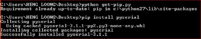
At the cmd type python get-pip.py to install after downloading otherwise type python -m pip install -U pip for ungrading.
3) Download and install pyserial from this link
At the cmd type pip install pyserial for installation.
Example screen shot of the commands in the cmd
Starting out
I came across this site which provided quite a comprehensive information which I think was quite useful to me in my opinion. I selected its "Hello world with serial ports" and borrowed their codes and modified them slightly. I suggested the codes be tested out in Arduino Uno first before loading them into the Attiny chips which I did.
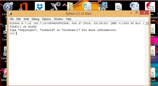
After all the python installations were done, typed in "IDLE(Python GUI)" in the search column as shown below.
You will see the Python 2.7 Shell open up on your desktop.
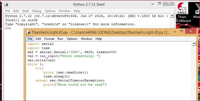
Clicked on File followed by New File. Copy and paste the python codes into this shell and save the file as ***.py. Finally close this shell.
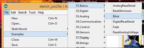
Now start up the Arduino and open up the blink program and load it into the Arduino Uno.
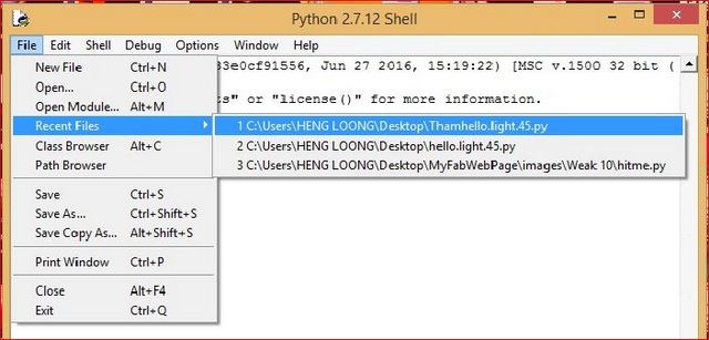
Going back to the Python 2.7 Shell, click File and Open the saved file or Recent File.
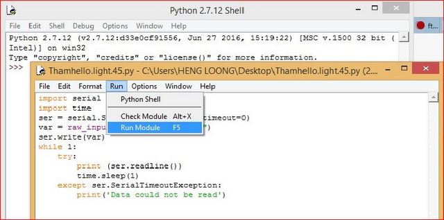
Click on Run and Run Module F5
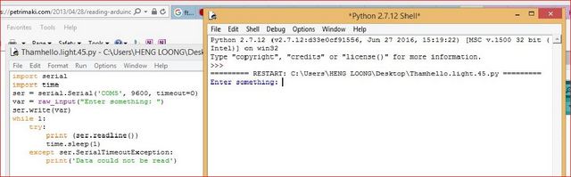
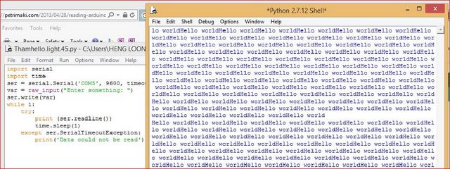
Now you will see the program running. Entered a single character and press Enter
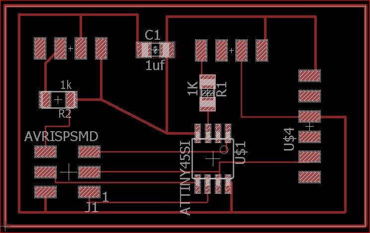
The design was translated onto the PCB as shown below.
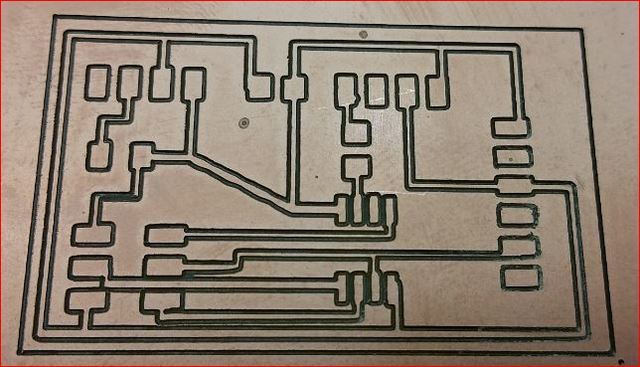
PCB after routing
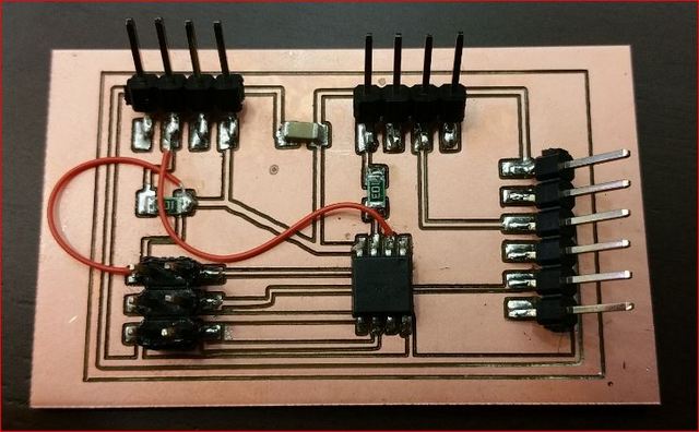
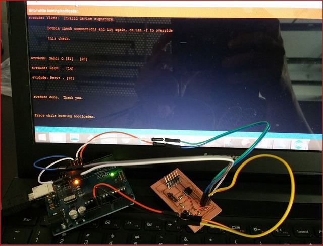
After the PCB was populated with components, I found some connections between components and terimal points were open circuit. Therefore, in order to save time and re-establish connections, I used wires re-established the connections. The picture showed the results.
Tried to bootloader the Attiny45 several times but all attempts failed to succeed.It kept displaying "Error while burning bootloader"
Finally I decided to terminate all actions to any further reproduction of any related PCB because it will continued to waste my time.
Doing the alternative
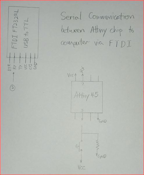
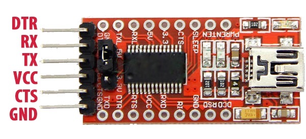
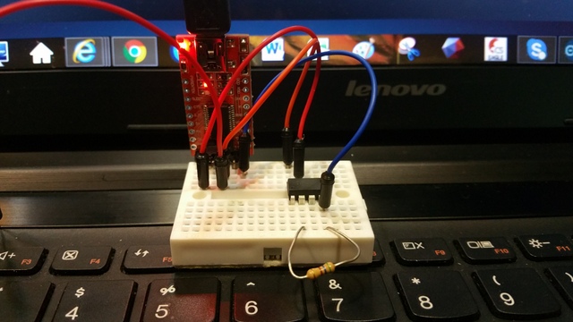
I hooked up the circuit as shown below according to my circuit sketch. The print messages will be dependent on the switch ON or OFF position.Only the RX of he FTDI was used because the pin 2 of the Attiny45 was programmed as the TX.
Hard wiring up the circuitry.
Followed by stardard procedure of bootloader and loading of the program into the Attiny45 chipset which I will not repeat. Please note the changes in messages when the switch; simulated by a jumper wire connected to a 5V terminal; is being activated and de-activated.
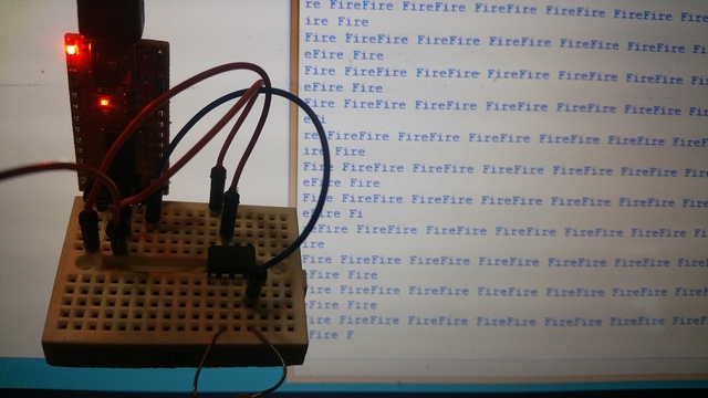
Message displayed Fire Fire when switch is OFF
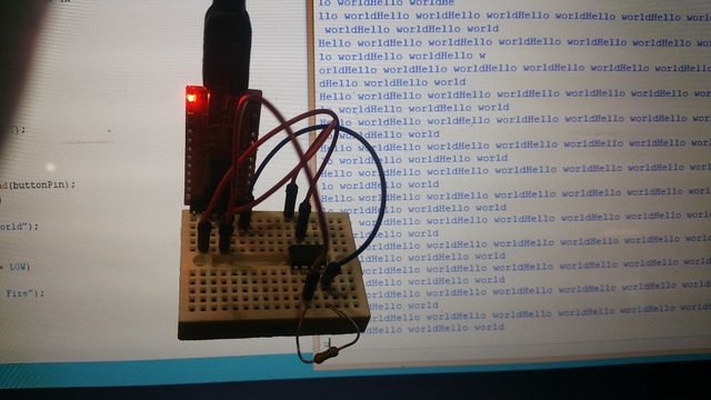
Message displayed Hello World when switch is ON
Here is a video presenting the successful communication between serial converter from Attiny45 to computer.
The working files for the Attiny45 and Python can be downloaded when you right click on the names and "Save Link As".
The Real Working Interface
Thanks to Steven for helping me out with another python programming. I was very bad with software programming and couldn't understand enough of the software, thus only able to achieve half what was required in this assignment.
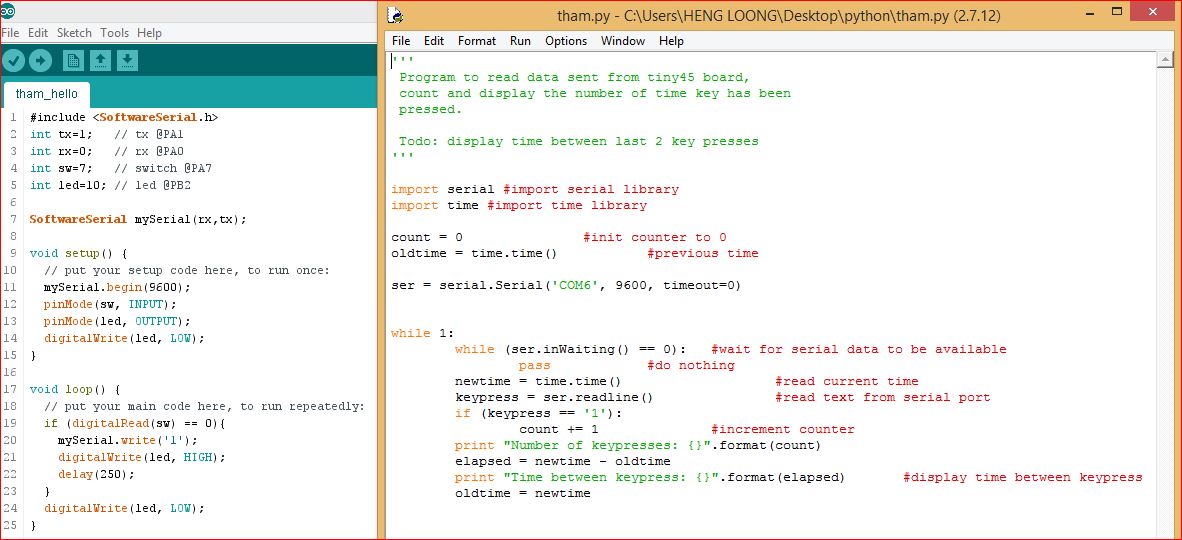
Screen shot of both the programs
Both working programs can downloaded here; Attiny45 and Python (Right click and Save Link As)
These two files were written by Steven, I didn't contribute any to it but tag along with a little bit of understanding. I still got much to learn on Python. Please view the video below.
Working of the Program
Originally, it will count the number of times the button was pressed and each time pressed will be indicated by a LED. At the same time, the timing between the presses of the button will be display together.
I decided to modified the program slightly. The display and LED lighted up will be continuous and will deactivated when the button was pressed. The display will indicated the timing of the button NOT pressed.
My comments
I'll will try Python programming again and will explored the workings with Tkinter.
I hope used it to combine it with bluetooth technology and send signals wirelessly to collect data as well as to control devices remotely.